Increase Torque and Speed In Stepper Motor

In most contest people using stepper motors struggle to make a confortable run due to the slow speed of the stepper motor and a poor torque . Unipolar motors have lesser power than their bi-polar counterparts but then there are ways to make your unipolar stepper work better than what it does now.

First You can have a look at the stepper motor control mechanism here
so in that post we’ve seen that the pulses are given in the order as below.

1000
0100
0010
0001

Now this will do a good job and give you a smooth running robot. But another good alternative to run your unipolar motor with greater torque and speed is to give the pulse the other way as below

1100
0110
0011
1001

This sequence will do the magic for you. Bu the robot will have a bit rough run compared to the single line sequence given previously.The two line drive will show you how fast your steppers can run with an appreciable torque.

Try it.

Servo Motor

You have all the way known only mototrs that rotatewhen you give in power?.Well did u want to have motors  that can be positioned in a particular angle them move them to different location. If you are making a robonoid u can’t think of any other motor than a Servonmotor.
This motor has an inbuilt circuitry to position the axle in a particular position based on the pulse width to its input. Varying the pulse width will result in changing the position of the motor.

This motor will help you make your bot in many ways. you may use it to steer the front wheel of your back wheel driven robot .You may happily use it to make a humanoiid arm movement system or just about any jijnt for the humanoid. i guess it is or great help when u can accurately position your motor. Afterall having a full control non what you do is what everyone will want.

How It Works 

I guess it is straight forward. You may see in the picture below,The pulse width of the input is shown on the left and you may see the different postion of the motot axle to your right.

Now you may generate this pulse using your microcontroller very easily or use a 555 to generate various pulsewidth using a variabl POT at the frequency determining pins. i guess things are pretty clear. If you do not know how to do this using 555 son worry i’l get that to you soon.Will also get the MicroC code for steering soon.

If you are beginig to make a bot donot goto DC motor but go for Servomotors cos they give a good torque.hey does it sound contradictory???. Did i say that we can adjust the postion of the axle then how de hell to make it run continuously. Well there is a small hack that you’l find all around the internet to do that. So guys try using this motor. It will make a good Geared DC motor with an inbuilt circuitry.

Do use it.Do  Comment your feedbacks.
–Madan

Exact Circuit and MicroC code for stepper motor

Well saw that people still are having quite some doubts on the stepper motor post that i had put up. so i thot to make that abstact clear i better put the exact circuit and the code here.

The exact circuit to connect the stepper motor to 16F877A is given below

In this the common is connected to the 16V supply(12 v is actually enough actually higher current drives the motor better as far as i know*). If u are new here and donot know how to find the common line in a unipolar Stepper motor then see here

The MicroC code for running the motor is as below.
void main()
{
TRISB = 0x00;
PORTB = 0x00;

//routine to move in one direction
for (i=0;i<50;i++)// increse i=50 no i=100 to cover double the distance
{
PORTB=0x80;
delay(20ms);
PORTB=0x40;
delay(20ms);
PORTB=0x20;
delay(20ms);
PORTB=0x10;
delay(20ms);
}

//routine to move in the other direction

for (i=0;i<50;i++) // increse i=50 no i=100 to cover double the distance
{
PORTB=0x10;
delay(20ms);
PORTB=0x20;
delay(20ms);
PORTB=0x40;
delay(20ms);
PORTB=0x80;
delay(20ms);
}
}

There are much easier ways to write the above code but then i am not worried about the memory it’l take nor have any pressing need to keep my code small and trim ,so i guess this will make you absolutely clear of what i’m trying to do to make my motor run.

If you din know MicroC well,let me brief. The line PORTB = 0x80 (1000000)makes my 8th pin of the PORT “B” that’s b7 pin or the 40th pin go high.The next line PORTB = 0x40(01000000) will make the 39th pin go high and all other low.

Now whenever the pin at the input of the ULN2003 goes high say pin 1 the output pin 16 drains the current throuh the motor thus completing the circuit from supplt 16V through motor to the ground in that line. When you keep doing this in series as i called it the abcd pulse the motor will rotate . When your reverse the pulse order the motor rotates in the other direction. As simple as that. For most robotic application atleast at contest level you may use this circuit uinless you go for bigger stepper motors that need more current to drive and is greater than the 500mA that the ULN2003 can sink!!
i guess i was clear about using ULN2003 to drive a sstepper motor. pl post your comments and doubts
–Madan
I like keeping all my circuits small and simple and not crowd it with resistors and capacitors.Afterall its a hobby and we need not complicate it.Cheers.

Make A IR Based Mice Robot

Well this is just a small mousey bot that can be make quickly from you old computer mouse froM the junk. The small DC motors would give it the speed and it'l almost not his and obstacle but avoid and keep running around on the floor. IR sensors would form the eyes of the bot so that it doesn't his obstacles. It will make a cool bot to show to yopur friends and put them in awe ! ,come lets get it done.

The basic concept is this way:
–>The two motors on the side propels the mouse fast in front
–>When an obstacle is detected in front the signal From IR is stops one of the motor from moving thus turning the bot to one side.
–>So the bot never hits and moves like a real mouse searching its way through.

As you can see in figure A) the two motors on the side propels the bot in front and then once the front IR recieves the presence of obstacle then the one of the motors stops moving thus rotating the bot to one side.The key feature that makes the bot ammusing is the speed at which it moves due to the motor.

Mechanical Setup:-
There's actually nothing much as mechanical setup. Just stick two motors on eithr side ot the mouse as show in fig A) below. It must be inclined as shown in figure B) which is its front side view.


Circuit Involved :-

–>Citcuit involves just two 7805 regulator and one BC107 transistor.
–>i guess ouy are able to see the circuit involved here.
–>The two motors runs on direct supply from the battery with a 7805 regulator in between.which is to just isolate the supply to the other motor when one motor supply is grounded
–>When the IR sensor detects the obstacle it willl give a 5v signal which drives the Transistor and groud the supply to the motor 2 thus stopping it.
–>While motor 1 is still running the bot turns right.
–>As soon as the IR sensor stops detecting the obstacles it drives the other motor too driving the bot in front.

If you have even a little basics in electronics you can follow this circuit. In case you'l need explanation please leave a comment.

Madan
P.S:-
The Ir cicuit need to be the one i suggested only to get it working properly. I have given the links on all the words "IR sensor" above. Take a lookj at theat and design the IR sircuit for this bot.

–>For the IR circuit vitis my post about IR sensors. Stessing this because most other IR detectors availabe on the net may not give 5v on signal detection but mine wiil hence stressed it a bit too much.

Stepper Motor Driver Circuit

Have you been searching for a goot damn circuit to drive your stepper motor?? Well even i did when i was learning robotics. Most stepper motor circuits that are available onlne have a bunch of transistors, Sometimes power trnsistors too quite a complicted circuit that drives you away far frm using it. Well i felt for most robotic use the stepper motor can be driven by a simple ULN2003 IC that costs just 12 bucks in my backyard.


The above are the most common types of stepper motors that you’l find in the market.

There are two types of stepper motor that normally is used.1)Unipolar 2)Bipolar . In simle terms they can be thought about like this. In unipolar there are 5 wires.One common wire and four wires to which power supply has to be given in a serial order to make it drive. Bipolar (not normally used in robotics) can have 6 wires and a pair of wires are given supplt at a time to drive it in steps.

STEP ANGLE :The angle with which the stepper motor turns for a single pulse if supply toone wire or a pair is called step angle.

Driving a stepper motor:

1) Identify the wire : Common and windings

Continue reading “Stepper Motor Driver Circuit”

Transistor as a switch

This circuits can help begginers to understand a transistor and use it for their ciruits. i will explain the general working of the transistor as a swithch and finally will give you few ideas of how all i used it.

Binary Output with a transistor:
1) Design a circut which allows a PIC processor to drive an LED array. This LED array has the following properties:


Vf @ 80mA = 10.2V ( six red LEDs are placed in series, giving 6 x 1.7V = 10.2V)
Assume that the PIC is only capable of driving 10mA at 5V.
Step 1. Find a transistor which can withstand 80mA.

110 < hFE < 450 ——>meaning you can count on a gain of atelast 300

max IC (Sat) = 200mA ——>meaning this can take 200mA. 80mA is quite small rite.

VCE(Sat) = 0.25V ——>a rough estimate of VCE at saturation

VCEO = 45V ——->meaning this transistor can take +45V when turned off

Step 2: Find a power supply bigger than 10.2V. Arbitrarilly assume a +24 supply.

Step 3: Find Rc to limit the current to 80mA

RC =( 24V-10.2V-0.25V)/ 80mA = 170 ohms

Step 4: Find RB to saturate the transistor. At the lowest gain, to put you just at the point of saturation,
Ib = ICE/hfe = 80mA /150 = 534uA —->150 is typical Hfe for BC107B in datasheet*
RB = 5V-0.7V/534uA = 32kohm

Pick R smaller than this to assure you saturate this stage. Let R = 10k.

switchIn this pic that i got from a random site kindly overlook the ZTX1051A transistor with Hfe>300. i have shown you calculations for BC107.

000000000000000000000000000000000000000000000000000000000000000000000


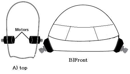
2) Design a circuit whichuses a single output from the PIC processor, and allows a PIC processor to drive this motor in the clockwise direction at either 0% speed (0V) or 100% speed (+5V). Assume the motor draws 470mA at +5V.

Step 1: Pick a transistor. I'll stick with a BC107 because I like this transistor.

Step 2: Add the motor to the collector. You don't need a current limiting resistor since the motor's armature resistance and back EMF limit the current to 470mA @ 5V.

Step 3: Add RB to saturate the transistor. Worst case, when the gain is minimum (300) and you're just at the point of saturation:
IB = ICE/Hfe = 470mA/150 = 3.14mA

RB = 5V-0.7V/3.14mA = 5.48kohm

Step 4: Just to make sure that you saturate the transistor, make Rb smaller than this. Let RB = 2k.note: The inductance in the motor stores energy in a magnetic field. When the current is turned off (the transistor turns off) the energy in the field has to go somewhere. To save the transistor, place a diode across the motor to allow the collapsing field to drive current through the diode – saving the transistor

motor
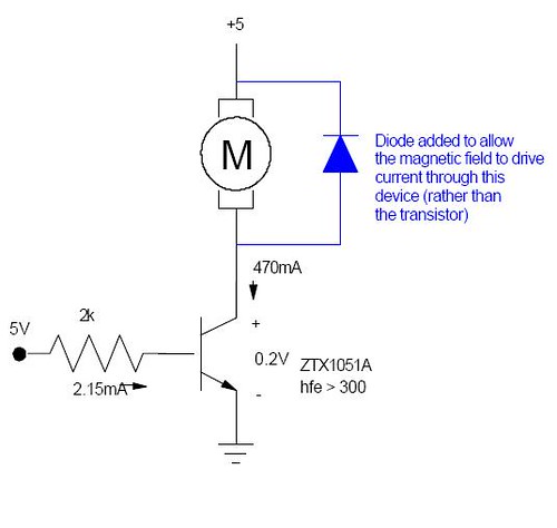
again the ZTX1051A is replaced by BC107 and the current at 2k at base resistance is 3.14mA.

000000000000000000000000000000000000000000000000000000000000000000000


3) Design a circuit which can drive the motor forward and in reverse using transistors:This is the transistor version of my ULN2003 H-Bridge
You can use the same circuit as before, only add another NPN and two more PNP transistors. The equations work out
the same for each transistor:
NPN:BC107
OFF: put the input to 0V. This assures that 0A flow through the diode.
ON: make RB = 2k to saturate this transistor when 470mA flow though it.

IB > 470mA/Hfe = 3.14mA

RB < 5V-0.7V/1.57mA = 5.48kohm

Let RB = 2k.

PNP: BC177(since I picked a transistor with the same gain (Hfe or b)
OFF: put the input to +5V. This assures there is no potential across the base diode and no current flows.
ON: Make RB = 2k to saturate this transistor when 470mA flows through it.
IB > 470mA/Hfe = 3.14mA

RB < 5V-0.7V/3.14mA =5.48k
Let RB = 2k

bridge

That will do…..

 000000000000000000000000000000000000000000000000000000000000000000000

MY IDEAS TO USE TRANSISTORS AS SWITCH:

1) I connected my local FM radio reciever to my parallel port. There are only two switches to operate it. one for selecting channel and the other for reset . just connect it this way below and you can write a code in VB or C to address the ports and to scan or reset.

fm

The two black thigs are the switches.. just pic the two sides which the switch shorts on pressing and make this combination and get your electronic switch working.

2) I have connected my calculator and microcontroller using the same concep.. I will put those pics later as my friend is havin the digi as of now!!

Cheers trying the circuits. Keep giving your coments plas (it will cheer me up!!) –Madan

H bridge with ULN2003

Brand new circuit that you will fin nowhere on the internet.. he he cos i found this out. Well runnig DC motors for a robot you can very happily use this low cost circuit that using a L293D for Rs175!! in this circuit i have put a H-Bridge circuit with u ULN 2003 Ic that costs just 12 bucks.

PIC3

okie now i assume the circuit is very easy to understand.. A" and B" are the two control signals.. givin a high to any one of them wil make the motor move in one direction while a signal to the other will mover it in opposite direction.The main asvantage of this circuit being that you can adjust the voltage applied to the motor by cahgig the sypply at collector of the BC107.(sorry people for not puttin " >" at the emitter. assume it to be down!!) i almost got my recor torn by my techer for not putyting the arrow at the emitter in my secon semester of college!!!<>

 Its all about !!!